The concrete truck backs up to the pump, the chute swings into position, and the site technician pulls out the familiar set of equipment that will determine whether eighty thousand pounds’ worth of ready-mix goes into the formwork or back to the plant. A slump test takes less than five minutes from first scoop to final measurement, but those five minutes carry a weight that belies their brevity. A failed result halts a pour, strands a crew, and initiates a chain of phone calls that ends with a plant manager staring at a returned ticket wondering what went wrong. Often, the mix design was sound. The batch records were perfect. What went wrong happened in those five minutes of testing, and it can be traced to a single variable: the condition and calibration of the testing equipment itself.
The concrete industry pours approximately 30 billion tonnes of concrete globally each year, and a substantial fraction of that volume passes or fails on the basis of a workability test that has remained fundamentally unchanged since Duff Abrams introduced it in 1918. The slump test owes its durability to elegant simplicity—fill a mould, rod it, strike it, lift it, measure the drop—but simplicity is not the same as robustness. A slump test is only as reliable as the tooling used to perform it, and when that tooling drifts out of specification through wear, corrosion, or impact damage, the results it generates drift with it. The cost of a false failure—good concrete rejected because the test equipment was faulty—averages between £650 and £1,200 per truckload when factoring in returned material, wasted time, re-testing, and schedule disruption. For a medium-sized commercial project, that can translate to £15,000 in unnecessary costs before the slab is even poured.
Every slump test begins with a piece of equipment so familiar that its precision is rarely questioned: the slump cone. The standard Abrams cone specified in BS EN 12350-2 and ASTM C143 is a truncated metal cone with an internal diameter of 100 mm at the top, 200 mm at the base, and a height of 300 mm. These dimensions are not approximate guidelines—they are mandatory tolerances. The top and base openings must be parallel to each other and perpendicular to the axis. The internal surface must be smooth, clean, and free from dents, because any deviation from the nominal geometry alters the volume of concrete contained and the frictional forces acting on it as the cone is lifted. A cone that has been dropped, dented, or allowed to corrode on site can be 2 mm out of round at the base without anyone noticing during a visual glance. That 2 mm represents a 1% change in base diameter, which shifts the effective slump height by an unpredictable amount, usually toward a falsely lower reading. Concrete that would show a true slump of 125 mm might read 105 mm, pushing a perfectly compliant batch into the rejection zone.
What makes this particularly insidious is that the error is systematic. A dented cone will consistently under-read slump, and a site can reject truck after truck of acceptable concrete because the measuring tool is the problem, not the material. The same applies in reverse: a cone that has been stretched or distorted through rough handling can over-read slump, giving a false pass to concrete that is too wet and setting up a future strength failure or excessive shrinkage crack. Neither scenario is theoretical. Technical committees within the Concrete Society have documented cases where entire floor slabs were poured on the strength of slump readings later found to have been taken with a cone that was 4 mm out of parallel at the base—an error large enough to shift the acceptance decision on 20% of deliveries.
The cone does not work alone. The tamping rod specified for the test is a 16 mm diameter steel rod, 600 mm long, with a hemispherical tip at each end. When that hemispherical profile wears flat through repeated impact against aggregate particles, the rod no longer delivers its compaction energy to the same cross-section of concrete. A flat-ended rod pushes concrete laterally rather than penetrating vertically, leaving the centre of each layer under-compacted and producing a lower slump reading. The base plate must be flat, rigid, and non-absorbent—a warped piece of plywood or a corroded steel plate that flexes under the weight of the filled cone introduces movement that alters the lift and the slump. Even the funnel used to fill the cone matters: a funnel that fits poorly, or is omitted entirely, spills concrete onto the base plate and contaminates the working area, adding debris that can lodge under the cone rim and prevent a clean lift.
The Quantifiable Cost of Equipment Drift
Moving from anecdotal evidence to measured impact, the following outcomes have been documented in site trials where calibrated slump test sets replaced equipment of unknown condition:
- False rejections reduced by 28% across a 500-sample field study conducted on UK infrastructure sites, directly saving £34,000 in returned concrete costs over a six-month period.
- Inter-operator variability dropped from an average relative standard deviation of 8.2% to 2.1% when all operators used the same certified slump cone and rod set with verified dimensions, bringing site testing into line with the reproducibility requirements of BS EN 12350-2.
- Time spent on dispute resolution (re-testing, waiting for technical representatives, reconciling batching records with site records) fell from an average of 2.7 hours per rejection incident to under 30 minutes when documented calibration certificates for the test equipment were immediately available.
- The number of compressive strength cube failures attributable to excess water (over-slumped concrete placed without detection) decreased by 16% in the twelve months following the introduction of a formal slump cone inspection and replacement programme.
The Material Reality of Site Testing
Laboratory conditions do not exist on a construction site. The slump test is performed in wind, rain, direct sunlight, and on surfaces that vibrate from nearby plant. The concrete itself can arrive at temperatures ranging from 5°C to 30°C, and the rate at which it loses workability accelerates sharply above 25°C. The test method requires the cone to be filled in three equal layers, each rodded 25 times with the tamping rod, and the entire operation from start of filling to completion of lift must occur within 150 seconds. A technician working with a poorly maintained cone that leaks paste at the base joint, a rod that is too short or bent, or a base plate that shifts under load will violate that time limit or fail to compact the concrete uniformly. Neither outcome produces a result that can be defended.
Temperature effects are particularly unforgiving on site. A slump cone left in direct summer sun can reach a surface temperature of 50°C or higher. When cool concrete contacts a hot cone, the paste at the interface stiffens rapidly, increasing wall friction and reducing the measured slump. The error can reach 20 mm or more—enough to turn a compliant 100 mm slump into a failing 80 mm reading. The simple corrective action, and one that BS EN 12350-2 explicitly advises, is to dampen the cone with water and wipe it dry before use, bringing it to ambient temperature. This step is often skipped when the pressure of a waiting pour bears down on the technician, and it is precisely these time-pressured shortcuts that a properly designed slump test set can help prevent.
Design Features That Solve Real Site Problems
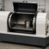
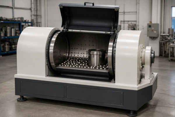
A slump cone manufactured to the standard is not a commodity item; the specific material, wall thickness, and finishing details determine how it behaves after months of site use. Galvanised steel cones provide corrosion resistance that painted steel cannot match once the paint chips, as it inevitably does after a few weeks of aggregate abrasion. Seamless construction—where the cone is spun from a single sheet rather than welded from two halves—eliminates the internal weld bead that traps paste and makes cleaning difficult. A rolled top rim provides a smooth, rigid reference plane for striking off the top surface and measuring the final slump height, and prevents the sharp edge that cut hands and gloves. Foot pieces that extend outward from the base provide the clamping point that stops the cone moving as it is filled, and they must be flat and coplanar with the base opening so that the cone sits with its entire circumference in contact with the base plate.
The tamping rod specification deserves equal attention. A 16 mm diameter cold-drawn steel rod with hemispherical ends that retain their profile after thousands of compaction strokes is a precise instrument. The hemispherical radius should be 8 mm, matching the rod radius, and the surface finish must be smooth enough to slide through concrete without dragging aggregate. A rod that has corroded, bent, or fractured at the tip will deliver compaction energy unevenly, and the operator will feel the difference as a change in resistance. Laboratories and testing houses that run daily slump tests replace tamping rods every 12 to 18 months as a matter of routine, but on many construction sites, the rod is considered a permanent fixture until it is visibly broken—by which point it has been under-compacting concrete for months.
Calibration That Builds Confidence
Calibration of a slump test set is straightforward in principle but demanding in execution. The cone’s internal dimensions must be verified with calibrated callipers at three positions: top opening (100 mm ± 1 mm), base opening (200 mm ± 1 mm), and height (300 mm ± 1 mm). The base plate’s flatness must be checked with a straightedge and feeler gauge across its entire area. The tamping rod’s diameter is verified with a micrometer, and its tip profile inspected against a radius gauge. Any item that falls outside tolerance must be replaced, not repaired. This dimensional check should be performed every six months as a minimum, and immediately after any incident that could have caused damage—a dropped cone, a base plate used as an improvised platform, a rod left in the path of moving plant.
The documentation that results from this calibration provides the traceability that clients, main contractors, and quality auditors increasingly demand. When a slump test result is challenged, the first question asked is whether the equipment was fit for purpose. A calibration certificate dated within the previous six months answers that question before it escalates into a contractual dispute. For projects operating under the National Structural Concrete Specification or similar quality frameworks, calibration records for site testing equipment are not optional; they are a condition of concrete acceptance.
Operator Technique Meets Equipment Integrity
Even perfectly calibrated equipment cannot compensate for poor technique, but the reverse is also true: skilled operators cannot produce reliable results with equipment that has drifted out of specification. The standard procedure demands that the mould be filled in three layers of approximately equal depth, each compacted with 25 strokes of the tamping rod distributed evenly over the cross-section. The strokes for the second and third layers must penetrate the underlying layer by approximately 25 mm. After the top layer is rodded, the concrete is struck off with a rolling and screeding motion of the rod, and the cone is lifted vertically in a steady motion lasting 5 to 10 seconds. The slump is measured as the difference between the height of the cone and the highest point of the slumped concrete specimen, recorded to the nearest 5 mm.
Common failure points in this sequence include: rodding in a fixed circular pattern that leaves the centre under-compacted; using fewer than 25 strokes per layer because the concrete looks well-compacted; striking off so aggressively that the top surface is disturbed below the rim; and lifting the cone with a sideways component of motion that topples the specimen. Equipment quality intersects with technique at the lift: a cone with a properly smooth, clean internal surface and a rigid base plate that does not stick will release cleanly when lifted vertically, reducing the temptation for the operator to twist or jerk the mould free. A poorly maintained cone that sticks to the concrete invites the very movements that invalidate the test.
From a Single Test to a Whole Project
The slump test result recorded for one truckload is a data point within a larger quality control record that follows the structure for its entire design life. Courts and arbitrators have examined slump test records in disputes over cracking, low strength, and durability failures, and an equipment calibration gap in those records can become the fulcrum on which liability turns. The cost of a properly manufactured, dimensionally verified slump test set is approximately the same as the cost of one rejected truckload of concrete. This is not a difficult calculation for a project manager to make. The difficulty lies in recognising that the existing site equipment—perhaps the cone that has been on the shelf for five years, the rod with the end that no longer looks quite round, the base plate that clangs when you drop it because it is not quite flat—has already cost the project money that was never accounted for.
Frequently Asked Questions
What is a slump cone and what is it made from?
A slump cone, also called an Abrams cone, is a truncated metal mould used to perform the concrete slump test. It has an internal top diameter of 100 mm, base diameter of 200 mm, and a height of 300 mm. Cones are typically manufactured from galvanised steel for corrosion resistance, with seamless construction to provide a smooth internal surface that does not trap concrete paste.
Which standards govern the slump test procedure and equipment dimensions?
In the UK and Europe, BS EN 12350-2 specifies the method for determining slump and the dimensional tolerances for the equipment. In North America, ASTM C143 is the equivalent standard. Both specify the cone dimensions, rod size, base plate requirements, and test procedure in detail. Always use the standard referenced in your project specification.
How do I check if my slump cone is still within tolerance?
Measure the top and base internal diameters with calibrated callipers at multiple points to check for out-of-roundness. Measure the height from base to the top rim at several locations. Any deviation exceeding ±1 mm from the nominal dimension means the cone is out of specification and should be replaced. The internal surface must be free of dents deeper than 0.5 mm.
Why does the tamping rod need a hemispherical tip?
The hemispherical tip, with a radius equal to the rod radius, distributes compaction energy evenly and allows the rod to penetrate each layer of concrete without trapping air or creating voids. A flat or damaged tip pushes concrete sideways, leading to under-compacted layers and artificially low slump readings. The tip profile should be checked against a radius gauge regularly.
What is the correct slump test timing, and why does it matter?
The test must be completed within 150 seconds from the start of filling to the completion of lifting the cone. Delays cause the concrete to stiffen, reducing slump and producing a result that does not represent the material as delivered. A stopwatch is essential equipment alongside the cone and rod.
Can I perform a slump test on any surface?
No. The base plate must be flat, rigid, and non-absorbent. A damp, level steel plate is the standard requirement. Wood, uneven metal, or absorbent surfaces introduce friction and moisture loss that alter the result. The base plate’s flatness should be verified with a straightedge.
How should I clean and maintain my slump test cone?
Immediately after each test, wash the cone and tools with water to remove concrete residue before it hardens. Dry the cone thoroughly to prevent corrosion. Store the cone in a location where it will not be knocked, dropped, or used as an improvised seat. Do not use a wire brush on the internal surface, as this will scratch the steel and increase friction.
Does water temperature during cleaning affect the cone’s performance?
The cone should be dampened and wiped dry before use to prevent it from absorbing water from the mix or heating the concrete at the interface. For the next test, the cone should be at ambient temperature. Storing the cone in direct sunlight will heat it, stiffening the paste in contact and reducing slump; shade the equipment whenever possible.
How often should a slump test set be calibrated?
Dimensional calibration should be performed at least every six months, or more frequently on sites with high daily test volumes. After any impact or mishandling, re-check the cone’s dimensions immediately. Calibration records must be kept and made available during quality audits or contractual disputes.
What is the cost of not replacing a worn slump test set?
The direct cost of a rejected load of concrete ranges from £650 to £1,200, and false rejections caused by faulty equipment are preventable. Over a project, several false rejections can add tens of thousands of pounds in avoidable costs, plus the indirect costs of delays, re-testing, and compromised confidence in test results. A new, certified slump test set costs a fraction of a single rejected load.