In civil engineering, materials metrology, and industrial manufacturing, the precise characterization of granular materials is a structural safeguard. The aggregate gradation curve directly dictates the performance of finished infrastructure, from the compressive strength of structural concrete to the load-bearing capacity of asphalt road surfaces. For instance, a minor cumulative drift in the fine sand fraction can significantly alter the water-to-cement ratio of a concrete mix, leading to accelerated mechanical degradation, premature micro-cracking, and eventual structural failure. In high-volume industrial contexts, out-of-specification batches result in severe financial penalties, rejected raw materials, and extensive mechanical rework.
To mitigate these risks, modern laboratories must transition from manual, operator-dependent screening to highly standardized, automated separation systems. Moving beyond standard compliance checks to implement advanced mechanical separation equipment can reduce testing cycle times by up to 50%. It also increases screening accuracy by more than 80%, providing a reliable defense against the high costs of unplanned downtime and failed batch production.
Overcoming Mechanics and Wear Obstacles
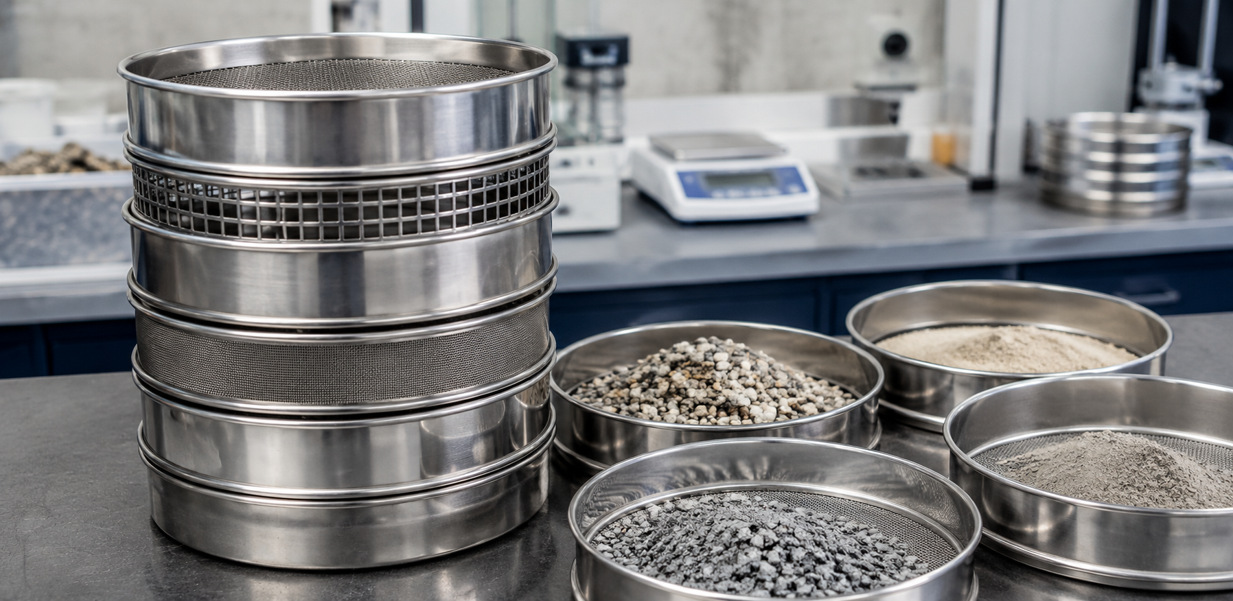
To maintain the strict accuracy demanded by international testing standards, laboratories rely on high-grade sieves that can withstand rigorous operational demands. These testing instruments are subjected to extreme physical forces, particularly when processing highly abrasive materials such as crushed granite, silica sand, or metallic carbides. Over thousands of operational cycles, particle friction inevitably erodes the wire alloy, causing wire thinning and localized mesh stretching. This physical degradation systematically alters the nominal opening sizes, allowing oversized particles to slip through and skewing the gradation data toward an artificially coarse profile.
Two distinct mechanical failures commonly disrupt the separation process: blinding and pegging. Blinding occurs when fine, moist, or electrostatically charged particles adhere to the outer surfaces of the wires, bridging across the apertures and forming a dense paste or skin that seals the openings. Pegging is a mechanical wedging phenomenon where near-size particles—typically those measuring between 75% and 125% of the nominal aperture width—become physically jammed within the individual mesh openings. Both issues reduce the screen’s active open area, causing throughput to drop and forcing correctly sized fine material into the oversize reject stream.
To resolve these physical limitations, laboratories must select the correct mesh alloy, frame design, and aperture geometry. High-grade stainless steel frames and wire mesh offer superior resistance to chemical corrosion and abrasive wear. In civil engineering laboratories where aggregate testing involves highly alkaline cement slurry residues, stainless steel prevents chemical degradation, thereby preserving the structural integrity of the testing grid.
The table below contrasts the technical characteristics and ideal applications of the three primary sieve designs manufactured by Capco:
| Sieve Type | Manufacturing Standard | Available Sieve Diameters | Aperture Range and Profile | Ideal Material Applications |
| Woven Wire Mesh | ISO 3310-1 / ASTM E11 | 38 mm to 450 mm (and 3 to 18 inches) | 125 mm down to 20 microns; square apertures | Fine dry powders, chemical pigments, pharmaceuticals, micro-aggregates |
| Perforated Plate | ISO 3310-2 / ISO 5223 | 200 mm to 450 mm | 125 mm down to 4 mm (square) and 125 mm down to 1 mm (round) | Coarse aggregates, coal, railway ballast, ores, heavy mineral materials |
| Wet Washing | ISO 3310-1 / ASTM E11 | 200 mm or 8 inches (4 or 8 inches deep) | Brass/stainless steel frames; options with fine mesh support backing | Soils with high clay/silt content, cohesive mineral slurred matrices |
Dynamic Agitation Mechanics
A purely vertical, up-and-down shaking motion is highly inefficient for particle stratification. Without a horizontal component, particles simply bounce in place, striking the same wire intersections repeatedly and increasing the likelihood of vertical pegging. Furthermore, purely vertical agitation fails to distribute the material bed evenly across the screen, leading to a localized pile-up in the center that chokes the active separation zone.
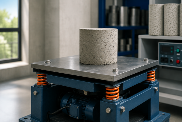
To achieve rapid, high-fidelity separation, advanced mechanical shakers employ a synchronized, double-action movement combining gyratory and jolting forces. This dual-action mechanism lies at the heart of the Capco Inclyno Series. The operational table of the shaker is permanently inclined relative to the machine’s central axis. The table does not rotate on its own axis; instead, it moves in a continuous, 3D gyratory orbit. This orbital motion generates a lateral shear force that forces the material to migrate outward, spreading it in a uniform, thin bed over the entire surface area of the mesh. Because the material is restricted to the plane of the mesh, particles are not thrown high against the inner walls of the frame, preserving testing efficiency and reducing dust generation.
Simultaneously, the shaker delivers a mechanical jolting action, physically lifting and dropping the entire stack over a short distance at a frequency of approximately 300 jolts per minute. This high-frequency impact serves two critical metrological functions:
- It fluidizes the material bed, initiating a process called kinetic stratification where smaller particles migrate downward through the voids between larger grains to contact the mesh.
- It provides a sharp, vertical acceleration that pops wedged near-size particles out of the apertures, preventing progressive pegging.
By presenting every single particle to the apertures at all possible spatial angles 300 times per minute, the gyratory-jolting action maximizes the probability of passage for every undersized grain.
The mechanical and physical specifications of these synchronized systems are detailed below:
| Technical Parameter | Inclyno Model 2 (SISHINC2) | Inclyno Model 3 (SISHINC3) |
| Motor Power Rating | 180W | 180W |
| Rotational Gyratory Speed | 2 RPM (inclined orbital table) | 2 RPM (inclined orbital table) |
| Mechanical Jolt Frequency | ~300 impacts per minute | ~300 impacts per minute |
| Operational Timing Control | Electronic digital timer, 0 to 99 minutes | Electronic digital timer, 0 to 99 minutes |
| Sieve Stack Capacities | 14 × 200mm (8″) OR 7 × 300mm (12″) | 14 × 200mm (8″) OR 7 × 300mm (12″) OR 5 × 450mm (18″) |
| Assembled Net Weight | 74 kg to 78 kg | 79 kg to 83 kg |
| Footprint Dimensions | 553 × 553 × 1395 mm | 475 × 705 × 1257 mm |
For environments where occupational health and safety regulations limit noise exposure, Capco provides specialized Sound Reduced Cabinets (product code SISHINCSOUND) for both models. These enclosures reduce mechanical noise by up to 28 dB(A), protecting technicians and ensuring compliance with workplace health, safety, and environment (HSE) standards without sacrificing analytical speed.
Critical Boundary Conditions
To maintain statistical validity, a mechanical separation test must operate within strict physical boundary conditions. The most common procedural error in industrial laboratories is sample overloading. When an excessive mass of material is introduced onto the top screen, the depth of the bed becomes too great. Under these conditions, the vertical agitation forces cannot fluidize the bed effectively, preventing the finer fractions from migrating to the screen surface. This leads to standard deviation errors, falsely indicating a coarser material gradation curve.
To prevent overloading, operators must calculate the maximum permissible load based on the open area of the wire cloth. The relationship between aperture width ($a$), wire thickness ($w$), mesh density ($M$), and the percentage of open area ($A$) is governed by the following equations:
$$M = \frac{1}{a + w}$$
$$a = \frac{1}{M} – w$$
$$A = \frac{a^2}{(a + w)^2} \times 100\% = (M \cdot a)^2 \times 100\%$$
For a standard 100-mesh wire cloth ($M = 100$ apertures per linear inch, or approximately $3.94\text{ mm}^{-1}$) with a wire diameter ($w$) of $0.1\text{ mm}$, the aperture width ($a$) is calculated as follows:
$$a = \frac{1}{3.94\text{ mm}^{-1}} – 0.1\text{ mm} = 0.254\text{ mm} – 0.1\text{ mm} = 0.154\text{ mm}$$
Using this aperture width, the percentage of open area ($A$) is:
$$A = (3.94\text{ mm}^{-1} \times 0.154\text{ mm})^2 \times 100\% \approx 36.8\%$$
Knowing that only $36.8\%$ of the physical screen area consists of open space emphasizes why aggregate loads must be strictly limited. Standard testing guidelines, such as ASTM C136, dictate that for opening sizes larger than $4.75\text{ mm}$ (No. 4), the material bed must be limited to a single layer of particles on the mesh during agitation.
Furthermore, standard testing procedures require the verification of the analytical endpoint. Rather than running the shaker for an arbitrary, fixed time, the true endpoint is reached only when the mass of material passing through any individual screen during one minute of continuous manual hand-sieving is less than 0.1% of the total dry sample mass. For large-diameter coarse aggregates where manual verification is physically impractical, testing facilities utilize 203-mm (8-inch) diameter reference screens to verify that the automated cycle time has achieved complete separation.
Wet Processing Protocols
When dealing with cohesive powders, high-clay soils, or micro-granulations (typically finer than 75 microns), dry separation methods fail completely. Ultrafine particles carry high surface-charge-to-mass ratios, generating strong electrostatic and van der Waals forces that cause rapid particle agglomeration. Under dry mechanical vibration, these fine particles clump together to form stable agglomerates that cannot pass through the fine wire mesh, severely distorting the lower end of the gradation curve.
To overcome these electrostatic and surface-tension barriers, laboratories utilize wet processing protocols. By introducing a liquid medium—typically demineralized water—operators can dissolve soluble binders, break down stubborn agglomerates, and wash fine silt and clay fractions away from the coarser sand grains. Wet washing is particularly suited for materials that are insoluble in water, structurally stable under heat up to $110^\circ\text{C}$, and chemically inert when exposed to liquid dispersion.
The standardized metrological protocol for wet separation is executed through the following stages:
- Initial Dry Mass Determination: The representative sample is dried in a ventilated oven at a temperature of $110 \pm 5^\circ\text{C}$ until it reaches a constant mass, which is recorded as the baseline dry mass ($m_d$).
- Chemical Dispersion (Soaking): The sample is placed in a deep container and fully submerged in water. For cohesive, clay-heavy soils, an anti-flocculent or dispersing agent, such as sodium hexametaphosphate $(\text{NaPO}_3)_6$ buffered with sodium carbonate $(\text{Na}_2\text{CO}_3)$, is added at a concentration of approximately 33 g/L and 7 g/L, respectively. The sodium ions replace divalent calcium and magnesium cations on the clay platelet edges, increasing the negative surface charge density and forcing the clay platelets to repel one another, breaking down the soil clumps. The sample is left to stand for a minimum of one hour, with regular mechanical stirring to ensure complete hydration.
- Suspension Rinsing: The fully dispersed slurry is carefully transferred onto a deep-framed wet washing screen. These specialized screens feature brass or stainless steel frames, typically 200 mm in diameter and up to 8 inches deep to prevent splashing and sample loss. Crucially, fine mesh screens (such as 63 or 75 microns) are supplied with a robust, coarse under-mesh support medium to prevent the fine wire cloth from sagging or tearing under the weight of the water column and wet aggregate.
- Controlled Sprinkling: A gentle, low-pressure water spray is applied using specialized dispersing nozzles to wash the fine particles through the screen. High-pressure spray jets must be avoided, as they can cause physical mesh damage or splash material out of the frame. The washing process continues until the discharge water running from the drain pan is entirely clear.
- Drying and Back-Weighing: The remaining material retained on the screen is carefully washed back into a collecting pan, ensuring zero material loss. The pan is placed in the laboratory oven at $110^\circ\text{C}$ to dry back to a constant weight, which is recorded as the retained dry mass ($m_r$). The cumulative percentage passing the reference screen is then calculated using the standard metrological formula:
$$\text{Percent Passing (< 75 }\mu\text{m)} = \frac{m_d – m_r}{m_d} \times 100\%$$
Metrological Calibration Standards
To establish traceability and ensure the reproducibility of particle size data, laboratories must adhere to strict international manufacturing and calibration standards, primarily ISO 3310-1 (for woven wire mesh), ISO 3310-2 (for perforated plates), and ASTM E11. These standards define the allowable statistical deviations for nominal opening sizes and wire diameters. For example, under ISO 3310-1, a standard $63\,\mu\text{m}$ screen has a permissible average opening tolerance ($y$) of $\pm 3.7\,\mu\text{m}$, meaning the calculated mean opening size across the mesh must fall strictly between $59.3\,\mu\text{m}$ and $66.7\,\mu\text{m}$. If the mean opening shifts to the upper limit of $66.7\,\mu\text{m}$, the mass of material passing through can artificially increase by up to 4%, invalidating the precision of the test.
To satisfy quality assurance protocols, instruments are categorized into three distinct verification tiers based on their level of statistical certification:
- Compliance: These are standard manufacturing-grade instruments. The manufacturer certifies that the wire cloth was woven in accordance with ASTM E11 or ISO 3310-1 standards, but no individual aperture measurements are recorded.
- Inspection: These instruments undergo optical calibration using an NIST-traceable digital comparator. A specified number of individual apertures and wire diameters are measured across both the X and Y grid directions. Statistical calculations are then performed to guarantee, with a minimum 99% confidence level, that the standard deviation of the openings falls within the maximum limits allowed by the standard.
- Calibration: This is the highest metrological tier, required for research and development or when testing results are subject to legal scrutiny. Calibration instruments undergo optical measurement of approximately twice the number of apertures required for the Inspection grade. This extensive data set increases the statistical confidence level to $99.73\%$, confirming that the aperture variations are exceptionally tight.
While optical microscopy is the traditional method for certifying new screens, it has major limitations for routine, in-house verification. Optical measurements inspect less than 0.1% of the total mesh surface area, require expensive specialized equipment, and are highly operator-dependent.
To resolve these in-house calibration challenges, laboratories utilize calibrated glass microspheres. These are single-shot, NIST- and NPL-traceable soda-lime glass beads manufactured with extremely narrow size distributions. Because the microspheres are highly spherical, their passage behavior is dictated purely by the physical width of the apertures, removing any shape-induced measurement bias. A single-shot vial containing millions of microspheres allows for the rapid and precise checking of over 80% of the active screen surface area in under two minutes.
The precise in-house verification protocol using glass microspheres is executed as follows:
- Step 1: Balance Calibration: Place the test screen nested in a clean collecting pan on a high-precision laboratory balance with a resolution of at least $0.01\text{g}$ and tare the scale.
- Step 2: Sample Loading: Select the specific single-shot calibration vial that matches the nominal aperture size of the screen under test. Pour the entire contents of the vial onto the mesh and record the exact starting weight of the microspheres ($w_s$).
- Step 3: Standard Agitation: Place the assembly on a mechanical shaker and agitate for exactly 2 minutes. This ensures that the spheres are evenly distributed across the entire surface and have multiple opportunities to pass through the openings.
- Step 4: Endpoint and Retained Weight Measurement: Remove the assembly, gently tap the frame to dislodge any near-mesh beads, and empty the pan containing the passed microspheres into a waste container. Without taring the balance, place the screen and pan containing the retained microspheres back onto the scale. Record the retained mass ($w_r$).
- Step 5: Mean Aperture Determination: Calculate the percentage of microspheres passing through the screen using the formula:
$$\text{Percent Passing} = \frac{w_s – w_r}{w_s} \times 100\%$$
Using the unique calibration certificate graph supplied with that specific batch of microspheres, the operator locates the calculated “Percent Passing” value on the Y-axis and reads the corresponding mean aperture size in micrometers directly from the X-axis. This provides a highly precise, traceable calibration of the screen’s actual physical performance.
Capco provides standard calibration bead kits covering a broad spectrum of aperture verification profiles, including fine and coarse classifications:
| Calibration Kit Size | Core Microsphere Nominal Range | Certified Bottle Package Size | Sieve Compatibility Guide |
| 20 Micron Set | 15 µm to 25 µm | 5 bottles, 0.8g per bottle | Verification of ultra-fine woven wire screens |
| 100 Micron Set | 90 µm to 112 µm | 5 bottles, 1.0g per bottle | Calibration of sand-fraction laboratory screens |
| 200 Micron Set | 180 µm to 212 µm | 5 bottles, 1.5g per bottle | Inspection of fine concrete aggregate screens |
| 1000 Micron Set | 850 µm to 1180 µm | 5 bottles, 7.0g per bottle | Verification of industrial abrasive sizing mesh |
| 2500 Micron Set | 2240 µm to 2800 µm | 5 bottles, 20.0g per bottle | Verification of coarse industrial aggregate screens |
Infrastructure and Asset Maintenance
Maintaining long-term metrological accuracy requires strict maintenance protocols and specialized laboratory infrastructure. A common cause of mechanical degradation is the physical deformation of the fine wire mesh during cleaning. Technicians must never use wire brushes, metal scrapers, or sharp picks to clear clogged or pegged particles, as these hard tools scratch the wire alloy, causing localized cold-working and permanently deforming the aperture dimensions. Proper cleaning is achieved using specialized ultrasonic baths or soft nylon bristle brushes, applying gentle force to the underside of the mesh.
Furthermore, wet washing aggregate samples poses a serious risk to laboratory plumbing. Standard sinks are not designed to handle the heavy, highly abrasive sediment loads carried by wash water, which can lead to clogged drains, pipe erosion, and environmental non-compliance if fine silts enter public sewer systems. To prevent these infrastructure failures, testing facilities install dedicated stainless steel sieve washing tanks.
These heavy-duty washing tanks are engineered with several key features:
- Stainless Steel Construction: The tank body is fabricated from high-grade stainless steel to ensure long-term durability and eliminate the risk of oxidation and rust contamination in clean water circuits.
- Multi-Stage Sediment Baffles: Internal physical baffles are welded into the tank reservoir to slow the velocity of the incoming wastewater. This deceleration forces dense silt, clay, and fine mineral particles to settle to the bottom of the tank, isolating them from the main sewage discharge lines.
- Gooseneck Spray Arms: A flexible, spring-action gooseneck spray assembly equipped with a ceramic disk cartridge prevents water leakage and allows operators to direct controlled water streams at specific areas of the mesh.
- Reinforced Support Grids: Because a large aggregate screen loaded with wet mineral specimens can weigh several kilograms, the tank features a reinforced support grid. This heavy-duty mesh top safely supports the weight of the frames, allowing them to drip-dry directly over the reservoir after washing.
By implementing these structural controls, laboratories protect their diagnostic assets, extend the operational life of their equipment, and ensure that their daily material test data remains highly accurate and reproducible.
FAQ’s
How does physical mesh wear affect the statistical validity of an aggregate gradation curve?
Physical mesh wear directly leads to the degradation of testing accuracy by allowing out-of-specification coarse material to pass through stretched or eroded apertures. Over time, friction from highly abrasive minerals causes wire thinning and physical mesh deformation. This systematic error shifts the entire particle size distribution curve toward an artificially fine profile. Consequently, it can hide critical errors in material formulation, which can severely compromise the structural strength of concrete or asphalt matrices in civil engineering projects.
What are the manufacturing standards and aperture differences between woven wire and perforated plate screens?
Woven wire screens are manufactured to ISO 3310-1 and ASTM E11 standards, utilizing high-tensile wire alloys to produce fine, square apertures ranging from 125 mm down to 20 microns. This makes them ideal for analyzing fine powders, pharmaceuticals, and soils. Perforated plate screens are manufactured to ISO 3310-2 and ISO 5223 standards, featuring a solid metal plate with square openings from 125 mm down to 4 mm, or round holes from 125 mm down to 1 mm. Perforated plates are preferred for coarse geological aggregates, coal, and railway ballast due to their superior resistance to heavy impact and abrasion.
Why is the 3D gyratory-jolting action of the Inclyno shaker mechanically superior to traditional vertical-only shakers?
A vertical-only shaker forces particles to bounce in a fixed vertical trajectory, causing localized material build-up in the center and accelerating vertical pegging. The Inclyno’s dual-action system features an inclined sieve table that gyrates at 2 RPM without rotating on its own axis. This lateral movement spreads the material in a uniform, thin bed across the entire mesh. Simultaneously, the mechanical jolting action delivers approximately 300 vertical drops per minute, fluidizing the material bed for optimal stratification while continuously clearing wedged near-size particles from the apertures.
How does one mathematically calculate the percentage of open area on a standard wire cloth to prevent overloading?
The percentage of open area is calculated by establishing the mathematical relationship between aperture width ($a$), wire diameter ($w$), and mesh number ($M$), using the equation $A = (M \cdot a)^2 \times 100\%$. For a standard 100-mesh screen where the wire diameter is 0.1 mm, the aperture width is calculated as $a = (1/3.94) – 0.1 = 0.154\text{ mm}$. The resulting open area percentage is $A = (3.94 \times 0.154)^2 \times 100\% = 36.8\%$. Recognizing that less than 37% of the sieve surface is open highlights why aggregate loads must be carefully limited to avoid mesh blinding.
What is the precise chemical dispersion protocol required for cohesive soil analysis before wet washing?
For cohesive soils, the dry clods must be chemically dispersed to break up clay aggregates without damaging the primary grains. The sample is soaked in a solution containing 33 g of sodium hexametaphosphate $(\text{NaPO}_3)_6$ and 7 g of anhydrous sodium carbonate $(\text{Na}_2\text{CO}_3)$ per liter of water. The sodium ions replace divalent calcium and magnesium cations on the clay platelet surfaces, generating strong electrostatic repulsion forces that disperse clay clumps into individual primary particles. The mixture must stand for at least one hour with regular stirring before being rinsed.
How do Calibration-grade sieves differ from Compliance-grade sieves under international standards?
Compliance-grade sieves are accompanied by a standard certificate confirming that the wire cloth was manufactured in accordance with ISO 3310-1 or ASTM E11 tolerances, but no individual aperture measurements are recorded. Calibration-grade sieves undergo rigorous optical metrology using an NIST-traceable digital comparator, where approximately twice the number of apertures are measured compared to an Inspection-grade sieve. This extensive measurement provides a 99.73% statistical confidence level that the standard deviation of the aperture openings remains within extremely tight limits.
Why is the glass microsphere calibration method preferred over traditional optical microscopy for in-house verification?
Optical microscopy is highly expensive, operator-dependent, and typically inspects less than 0.1% of the total apertures on a sieve. Additionally, it generates conflicting data for the X and Y mesh directions. In contrast, calibrated soda-lime glass microspheres provide an NPL- and NIST-traceable check of over 80% of the active sieve openings in under two minutes. Because the microspheres are highly spherical, their passage is determined purely by the physical width of the openings, eliminating any shape-induced measurement error.
What is the operational purpose of a sound-reduced cabinet for mechanical shakers?
Heavy-duty mechanical sieve shakers generate significant noise through continuous high-impact jolting and metal-to-metal agitation. A Sound Reduced Cabinet (such as SISHINCSOUND for the Inclyno 2 or 3) is a specialized insulated enclosure designed to encapsulate the shaker. These cabinets reduce mechanical noise levels by up to 28 dB(A), ensuring that laboratories comply with workplace noise exposure regulations under HSE guidelines while protecting technicians from long-term hearing damage.
How does a sediment baffle system in a sieve washing tank protect laboratory plumbing?
Silt, clay, and abrasive sand washed from test sieves can quickly settle in PVC pipe bends, leading to severe blockages, mechanical pipe erosion, and potential environmental fines for discharge violations. A specialized sieve washing tank features internal stainless steel sediment baffles that force incoming wastewater to flow along a winding path, slowing its velocity. This deceleration allows dense mineral particulates to settle to the bottom of the tank reservoir for manual cleanout, preventing sediment from entering the municipal sewer system.
What is the procedure for verifying that a mechanical aggregate separation test has reached its official endpoint?
According to standards like ASTM C136, a sieving test has not reached its valid endpoint simply by running for an arbitrary length of time. The official endpoint must be verified by removing the individual sieves and hand-sieving each fraction over a clean pan. The separation is complete only when less than 1% by mass of the material retained on any given sieve passes through the mesh during one minute of continuous hand agitation. For larger sieve sizes where manual shaking is impractical, 203-mm (8-inch) reference screens are used to verify and calibrate the automated shaker cycle times.
Summary
Achieving absolute accuracy in particle size distribution is not merely a matter of lab compliance; it is a critical process of risk mitigation that directly impacts structural and operational safety. From selecting the optimal wire mesh alloy to employing the double-action mechanical agitation of the Inclyno Sieve Shaker, every variable in the separation process must be strictly managed to prevent aggregate gradation errors.
By pairing these precision instruments with rigorous metrological controls such as wet-washing protocols, glass microsphere calibration, and dedicated sediment-trapping washing tanks testing facilities protect both their diagnostic data and their plumbing infrastructure. Implementing a robust, standardized testing workflow with high-durability equipment ensures repeatable, traceable results that protect the bottom line, reduce unplanned downtime, and maintain the highest standard of quality control.