In structural engineering and asset management, evaluating the compressive strength of hardened concrete is critical for safeguarding structural integrity and preventing catastrophic material failure. Traditional concrete quality control relies heavily on casting and curing standardized concrete cubes for subsequent destructive compressive testing. However, when on-site issues arise such as a suspected low-strength cement batch, improper consolidation, or the gradual mechanical degradation of aging infrastructure engineers are forced to assess the concrete directly in-situ. Historically, this has required extracting physical cylindrical cores using heavy rotary drilling rigs. This invasive approach is not only logistically complex and labor-intensive but also presents severe structural risks, particularly in post-tensioned concrete elements where severing a high-tensile steel tendon could compromise the entire load-bearing capacity of the assembly.
Beyond the immediate structural hazards, destructive core testing introduces substantial secondary complications. The physical extraction process leaves voids that must be carefully patched with high-strength, non-shrink grout, adding material costs and labor time. Furthermore, the turnaround time for preparing, capping, and crushing cores in a laboratory environment can span several days, stalling critical construction schedules and escalating the cost of unplanned project downtime. To mitigate these expenses and preserve the physical continuity of concrete assets, structural engineers utilize non-destructive testing (NDT) methodologies. These surface-hardness and dynamic response techniques provide immediate, non-invasive insights into the material’s compressive strength profile, allowing rapid mapping of large surface areas without compromising the structural load path.
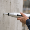
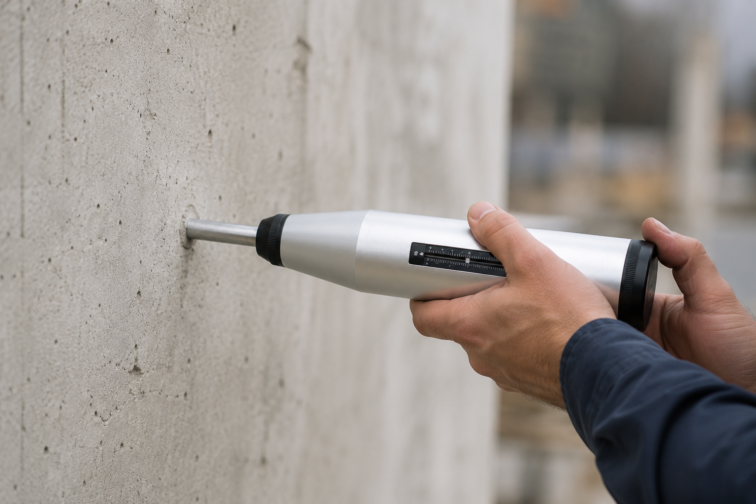
Among the array of non-destructive diagnostic tools, the spring-driven rebound instrument is the most widely utilized for localized hardness mapping. This mechanical device, commonly referred to as an impact hammer or Schmidt hammer, operates on a fundamental physical principle: the rebound of an elastic mass depends on the hardness of the concrete surface against which it strikes. During operation, the user presses the instrument’s hardened steel plunger perpendicularly against the concrete surface. This action gradually compresses an internal main spring until it reaches a release threshold. At this critical release point, the spring-loaded percussion weight is automatically unleashed, striking the back of the plunger and transferring its kinetic energy through the plunger tip directly into the concrete matrix. The rebound distance of the mass is recorded on a linear scale as a dimensionless rebound number, or R-value, which represents a direct empirical correlation to the surface compressive strength.
Mechanical Energy Thresholds and Device Configurations
To perform reliable assessments, engineers must match the impact energy of the instrument to the specific geometry and age of the concrete structure. The two primary mechanical configurations utilized in structural diagnostics are the Type N and Type L hammers. Each operates under distinct physical parameters designed to evaluate different material depths and structural thicknesses.
| Technical Parameter | Type N Rebound Hammer (e.g., Capco SKU: SCHMIDTN) | Type L Rebound Hammer |
| Nominal Impact Energy | $2.207 \text{ Nm}$ ($1.63 \text{ ft-lbf}$) | $0.735 \text{ Nm}$ ($0.54 \text{ ft-lbf}$) |
| Minimum Structural Thickness | $\ge 100 \text{ mm}$ ($4 \text{ inches}$) | $\ge 50 \text{ mm}$ ($2 \text{ inches}$) |
| Compressive Strength Range | $10 \text{ to } 70 \text{ MPa}$ ($1,450 \text{ to } 10,152 \text{ psi}$) | $10 \text{ to } 70 \text{ MPa}$ ($1,450 \text{ to } 10,152 \text{ psi}$) |
| Primary Structural Applications | Mass concrete, bridge piers, heavy slabs, foundations | Thin-walled precast elements, early-age “green” concrete |
| Risk of Localized Micro-Cracking | High on thin cross-sections or early-age structures | Low; preserves surface aesthetics and structural continuity |
The higher impact energy of the Type N hammer ($2.207 \text{ Nm}$) ensures that the stress wave propagates deep enough into the surface layer to yield a representative hardness index of the bulk structural element. If this level of energy is applied to thin-walled elements (under $100 \text{ mm}$ in thickness) or early-age “green” concrete, the impact can cause localized shattering, aggregate fracturing, or significant flexural vibrations. These vibrations absorb the kinetic energy of the percussion weight, resulting in an artificially low rebound reading.
Conversely, the Type L hammer ($0.735 \text{ Nm}$) minimizes structural and aesthetic damage, providing a highly repeatable non-destructive option for post-tensioning checks, early formwork stripping, and precast pipe inspections.
Physical and Mathematical Foundations of Rebound Hardness
The physical phenomenon governing the test is the propagation and reflection of stress waves across a material boundary. When the percussion weight strikes the plunger, a portion of the kinetic energy ($E_k$) is absorbed by the concrete through plastic deformation, micro-compaction, and localized heat generation. The remaining energy is elastically reflected back into the spring-driven mass, driving its rebound. A concrete matrix characterized by low density, high porosity, or insufficient hydration exhibits lower stiffness and compressive strength. Consequently, it undergoes greater plastic deformation, absorbing a higher fraction of the impact energy and yielding a lower rebound number ($R$).
Conversely, dense, highly consolidated, and fully matured concrete behaves as a more elastic body, absorbing minimal energy and returning a high $R$-value. To translate these empirical measurements into actionable engineering data, statistical regression analysis is used to establish mathematical relationships. While manufacturers provide generic conversion curves directly on the instrument body, these are calibrated under controlled laboratory conditions using specific aggregate types. For high-precision structural diagnostics, site-specific regression equations must be developed. The general linear relationship is expressed as:
$$f_c = A \cdot R + B$$
Where $f_c$ is the estimated compressive strength in MPa, $R$ is the measured rebound number, and $A$ and $B$ are constants derived from empirical correlation testing. For a wider range of concrete qualities, non-linear power or polynomial regression models are frequently adopted to improve curve fitting across the strength spectrum:
$$f_c = a \cdot R^b$$
Where $a$ and $b$ are empirical coefficients determined by correlating rebound indices with compressive test values obtained from physical core extractions or standard concrete cube testing.
Standardized Operational Protocols and Environmental Corrections
To ensure data repeatability and compliance with international standards such as BS EN 12504-2 and ASTM C805, field technicians must follow standardized operational steps. Failure to control the testing environment introduces statistical errors that can compromise structural compliance evaluations.
Test Area Dimensions and Surface Preparation
The designated test area must represent a minimum diameter of $150 \text{ mm}$ ($6 \text{ inches}$) and be located on structural elements with a minimum thickness of $100 \text{ mm}$. Engineers must avoid testing directly over shallow steel reinforcement bars (less than $20 \text{ mm}$ of concrete cover), as the high elastic modulus of the steel will artificially inflate the rebound numbers, leading to an overestimation of the concrete’s compressive strength. Areas exhibiting obvious defects, such as honeycombing, scaling, or high surface porosity, must be excluded from the test matrix.
Surface preparation is critical because the rebound hammer is highly sensitive to localized surface properties. The test surface must be ground flat using a medium-grain silicon carbide abrasive stone. This grinding removes surface laitance, loose mortar, paint, and shallow carbonation layers. Unprepared, rough, or textured finishes absorb kinetic energy through the crushing of micro-projections, which can artificially lower rebound values by several units.
Spatial Distribution of Impacts
To comply with both BS EN 12504-2 and ASTM C805, a minimum of 10 discrete impact measurements must be taken within each designated $150 \text{ mm}$ test area. To prevent the stress wave of one impact from influencing adjacent measurements, impact points must be spaced at least $20 \text{ mm}$ apart from one another and located at least $20 \text{ mm}$ away from any structural edges or shape discontinuities.
Anisotropy of Casting Direction and Gravity
The directional orientation of the impact hammer relative to the casting plane affects the rebound readings. During the placement and compaction of a fresh concrete pour, gravitational forces cause a microstructural gradient to form. Water moves upward through capillary action a process known as bleeding while heavier aggregates settle toward the bottom of the formwork. This segregation creates a denser, harder microstructure at the base of a pour and a more porous, water-rich layer at the top. When testing horizontal elements like structural slabs, technicians should ideally test the underside (the molded face). This surface exhibits a more uniform aggregate distribution and is less affected by bleeding than the trowelled top surface.
The physical direction of the test whether upward, downward, or horizontal requires correction due to the effects of gravity on the internal percussion weight. Upward testing against a ceiling works against gravity, reducing the impact velocity and requiring positive correction factors. Conversely, downward testing on a floor slab accelerates the percussion weight, requiring negative corrections. Modern digital rebound systems, such as the Silver Schmidt, address this issue by using optical encoders to measure the velocity of the impact and rebound directly, which yields a Q-value that is independent of testing angle and internal friction.
Moisture and Saturation Mechanics
The moisture state of the concrete surface significantly influences its surface hardness. Fully saturated concrete exhibits lower surface hardness and lower rebound numbers than the same concrete in a bone-dry state. Water trapped within the capillary pores of the cement paste is incompressible. Under rapid, dynamic impact loading, this water generates localized hydrostatic pressure that dampens the elastic rebound of the plunger. To establish reliable correlations, any comparative laboratory specimens such as concrete cubes should be tested in a saturated, surface-dry (SSD) condition to match field moisture baselines.
Chemical Alterations: Carbonation Depth
Carbonation is a chemical reaction that occurs when atmospheric carbon dioxide ($CO_2$) diffuses into the concrete’s pore network. It reacts with calcium hydroxide ($Ca(OH)_2$), a byproduct of cement hydration, to form calcium carbonate ($CaCO_3$):
$$Ca(OH)_2 + CO_2 \xrightarrow{\text{carbonation}} CaCO_3 + H_2O$$
Calcium carbonate has a significantly higher mineral hardness than hydrated cement paste, which densifies the surface and creates a hard outer layer. When the impact hammer plunger strikes a carbonated surface, it yields an artificially high R-value. This can cause engineers to overestimate the structural strength of older concrete by up to 50% if the depth of carbonation is not measured.
To prevent this, technicians must spray a 1% phenolphthalein alcohol solution onto a freshly exposed concrete profile. Uncarbonated concrete, which is highly alkaline (pH > 12), will turn bright pink, whereas the carbonated surface layer will remain colorless. If carbonation is detected, the hard layer must be ground away before conducting the rebound test.
Metrological Verification and Quality Assurance Protocols
The accuracy of non-destructive testing depends on regular calibration and verification of the equipment. Mechanical wear is an unavoidable reality under field conditions. Repeated impacts cause wear to the internal main spring, guide rods, and latch mechanisms, leading to calibration drift over time.
To maintain measurement accuracy, testing laboratories must follow a strict quality control loop:
- Anvil Verification: Before and after every major testing program, or after every 2,000 impacts, the hammer must be verified using a certified reference test anvil. Capco’s Test Anvil for Schmidt Hammer features a solid tool steel cylinder with an impact area hardened to $66 \pm 2 \text{ HRC}$ to serve as a certified reference standard.
- Execution of the Calibration Check: The test anvil must be supported on a rigid base, such as a concrete floor, to prevent energy dissipation through vibration. The operator performs 10 consecutive strikes on the anvil, recording each value.
- Statistical Filtering: The technician calculates the average of the 10 readings. Any single reading that deviates by more than 6 units from this average is discarded, and the average is recalculated. If more than two readings in the set are outliers, the entire test run is invalid, and the hammer must be inspected for internal friction or spring wear.
- Standard Target: A properly calibrated and serviced Type N hammer must yield an average rebound number of $80 \pm 2$ when tested on the anvil. If the device falls outside this range, it must be sent to a specialist calibration facility, such as Capco, which offers a dedicated recalibration and certification service under SKU: RE-CALIBRATION & CERT FOR TYPE N IMPACT HAMMER.
Multi-Modal Diagnostics: The SONREB Method
A primary limitation of surface rebound testing is its inability to evaluate the internal concrete matrix. Because the impact hammer only measures surface hardness, it cannot detect deep internal voids, cracking, or material changes. To address this limitation, the international engineering community utilizes the SONREB (SONic-REBound) method.
This multi-modal diagnostic approach combines the surface hardness measurements of the rebound hammer with Ultrasonic Pulse Velocity (UPV) measurements. While the rebound hammer evaluates the outer structural skin, the UPV instrument transmits high-frequency compression waves ($\text{P-waves}$) through the entire cross-section. The velocity of these acoustic waves ($V$) is directly proportional to the density ($\rho$) and dynamic modulus of elasticity ($E$) of the concrete:
$$V = \frac{L}{T}$$
$$E = \rho \cdot V^2$$
Where $L$ is the path length and $T$ is the wave transit time.
| Evaluation Parameter | Destructive Core Extraction | Surface Rebound (Impact Hammer) | Combined NDT (SONREB Method) |
| Invasiveness & Damage | High; leaves $100\text{mm}$ structural voids | None; minor superficial indentation | None; completely non-destructive |
| Data Acquisition Speed | Slow ($3\text{ to }7 \text{ days}$ lab turnaround) | Instantaneous on-site readings | Rapid on-site profile mapping |
| Relative Cost Profile | High (labor, equipment, patching) | Low (highly economical) | Moderate (requires dual-instrumentation) |
| Assessment Domain | Single, localized vertical cylindrical core | Superficial skin ($0 \text{ to } 30 \text{ mm}$ depth) | Full volumetric and surface density profile |
| Uncalibrated Margin of Error | $\pm 5\%$ (direct laboratory crushing) | $\pm 25\% \text{ to } 30\%$[cite: 7, 24] | $\pm 10\% \text{ to } 15\%$[cite: 7] |
| Calibrated Standard Error | N/A (primary benchmark) | $\pm 5 \text{ MPa}$[cite: 7] | $\pm 3 \text{ MPa}$[cite: 7] |
By combining these two datasets through empirical algorithms, engineers can mitigate the limitations of each method. For example, high moisture content lowers rebound hammer readings but increases ultrasonic pulse velocity. Conversely, high aggregate content can increase rebound values but scatter acoustic waves, reducing velocity readings. The SONREB method balances these conflicting variables, reducing the estimation error of in-situ compressive strength to within $\pm 3 \text{ MPa}$, providing a highly reliable and non-destructive alternative to core extraction.
Integration within the Concrete Verification Ecosystem
While non-destructive tools provide rapid structural surveys, they function as secondary diagnostics that require calibration against physical benchmarks. True structural compliance is anchored in standard laboratory testing, where fresh concrete properties are measured and cast specimens are mechanically crushed to verify mix designs.
Core Sample Preparation and Laboratory Curing
To establish reliable calibration curves, engineers prepare test cubes from fresh concrete batches. This process requires high-quality testing apparatus, such as Capco’s precision-engineered steel cube moulds, which are designed for durability and easy handling. Following the BS EN 12390-2 standard, the concrete is placed into the moulds in equal layers. Each layer is compacted with a standardized compacting bar requiring at least 25 tamps for a $100 \text{ mm}$ mould or 35 tamps for a $150 \text{ mm}$ mould or compacted using a controlled mechanical vibration table to eliminate voids and entrapped air.
After casting, the specimens must be covered with a plastic sheet and stored in a room-temperature environment ($15 \text{ to } 25^\circ\text{C}$) for 24 hours to prevent moisture loss and early-age micro-cracking. Once stripped from their moulds, the cubes are placed into heavy-duty, temperature-regulated curing tanks. These tanks utilize automated submersible heating elements and continuous water circulation pumps to maintain a uniform temperature of $20 \pm 2^\circ\text{C}$. Full water submersion prevents surface evaporation and ensures complete hydration, allowing the concrete to achieve its characteristic strength.
Mechanical Compression Testing
Once curing intervals are reached typically at 7 and 28 days the specimens are removed from the water tanks to undergo mechanical testing. The 7-day test provides an early indication, revealing whether the concrete has achieved approximately 65% to 70% of its target strength, which serves as a vital gatekeeper for continuing subsequent structural lifts. The 28-day test stands as the official benchmark for structural compliance.
Statistical Compliance and Plant Diagnostics
Relying on a single sample to verify an entire concrete delivery introduces statistical vulnerabilities. True structural compliance is assessed by analyzing groups of specimens cast from consecutive batches over a defined production period. This multi-sample approach accounts for the inherent variability of raw components like river sand, crushed limestone aggregates, and bulk ordinary Portland cement. Without standard deviation tracking, a single anomalous reading could lead to the unnecessary condemnation of a perfectly sound structural section.
Engineers track the running average of four consecutive, independent test results to evaluate the shifting performance baseline of the mixing plant. If the running average dips beneath the characteristic strength threshold, the batching parameters require an immediate adjustment. This statistical method helps differentiate between an isolated sampling error such as a poorly compacted field specimen and a systemic material issue at the production facility. Monitoring these trends closely reduces materials waste by optimizing cement content while maintaining a rigorous safety margin.
Ancillary Site Testing and Workability Controls
Before concrete is placed and cured, site engineers must verify its fresh properties to ensure workability and consistency. A durable concrete tray is an indispensable tool in this process, helping streamline concrete sampling, mixing, and curing procedures. Capco’s concrete trays are engineered to support materials testing excellence. Heavy-duty steel trays are ideal for rigorous laboratory use, while lightweight plastic trays are designed for quick field jobs. These trays prevent aggregate segregation and spillage when transferring fresh concrete to slump cones, air meters, or cube moulds.
For highly fluid mixes, such as Self-Compacting Concrete (SCC), technicians perform slump flow testing to evaluate unconfined horizontal flow and dynamic yield stress. Under the British Standard BS EN 12350-8:2019, the baseplate must be set on a firm, level surface and cleaned with a damp cloth immediately prior to testing. Moisture control at this boundary layer is crucial; a dry baseplate will extract water from the advancing concrete flow front via capillary action, increasing localized yield stress and restricting the spread.
The slump cone is filled in a single continuous lift without any tamping or mechanical vibration. The operator then lifts the mould straight up to a distance of $225 \pm 75 \text{ mm}$ in $3 \pm 1 \text{ seconds}$. Once the concrete stops flowing, the operator measures the largest diameter of the resulting circular spread and a second diameter perpendicular to the first. The average of these two measurements determines the final slump-flow value. If the difference between the two diameters exceeds $50 \text{ mm}$, the flow is considered highly asymmetrical, rendering the test invalid and requiring a repeat with a fresh sample.
Technical Reference: Common Sclerometric Questions
Carbonation is a chemical process where atmospheric carbon dioxide reacts with calcium hydroxide within the concrete’s pore network to form calcium carbonate. Calcium carbonate is significantly harder and denser than the uncarbonated cement matrix. When the plunger strikes this carbonated surface, the elastic rebound is increased, yielding an artificially high rebound number. This chemical modification can lead engineers to overestimate the internal concrete strength by up to 50% if the carbonation layer is not ground away.
FAQ’s
How does concrete moisture content affect the calculated R-value?
Excess moisture at the concrete surface dampens the impact energy. Liquid water trapped within the capillary pores is incompressible. Under dynamic, high-velocity impact from the plunger, this water develops localized hydrostatic pressure that absorbs energy and reduces the spring rebound velocity. As a result, wet concrete typically yields rebound values that are lower than those of dry concrete of equivalent strength.
What is the minimum structural thickness required for standard Type N testing?
To ensure reliable results, the concrete member under test must have a minimum thickness of 100 mm (4 inches) and be rigidly fixed within the structure. If the member is thinner than this threshold, the kinetic energy of the impact will cause flexural vibrations within the element. These vibrations dissipate energy that would otherwise drive the rebound of the internal mass, leading to artificially low rebound numbers.
How frequently should a rebound hammer be verified on a calibration anvil?
Best practice and standard operating procedures dictate that the instrument’s calibration must be verified using a certified reference test anvil before and after every major testing program, after every 2,000 impacts, or whenever the hammer has been subjected to a hard drop or rough handling. This routine check ensures that any internal spring fatigue or mechanical wear is identified before it can skew structural diagnostic data.
How do aggregate type and size influence the accuracy of the strength estimate?
The rebound hammer measures the hardness of the concrete’s surface layer, which consists of both aggregate particles and cement paste. If the plunger strikes a large, hard aggregate particle near the surface, the rebound number will be high. If it strikes a porous cement pocket, the reading will be low.
To minimize this aggregate bias, standard procedures require grinding the surface to identify aggregate boundaries and taking 10 spaced readings to average out these localized variations. Additionally, custom correlation curves should be established for mixes containing aggregates with atypical density or hardness, such as lightweight or high-density aggregates.
Why is it necessary to clamp concrete cubes in a compression machine during calibration?
During calibration or correlation testing, an unconfined concrete cube will slide or vibrate under the dynamic impact of the hammer’s plunger. This lateral movement absorbs a portion of the impact energy, reducing the rebound velocity and resulting in artificially low rebound readings. Clamping the specimen in a hydraulic press under a seating load equal to approximately 10% of its expected strength prevents movement, ensuring that the full impact energy is reflected back into the spring mechanism for an accurate reading.
What are the primary differences between ASTM C805 and BS EN 12504-2?
While both standards outline the same fundamental rebound principle, they differ in their specific guidance on surface preparation and verification. BS EN 12504-2 requires the technician to verify the hammer’s performance on a calibration anvil before and after each testing session. ASTM C805, while recommending anvil verification, focuses on detailed protocols for grinding textured surfaces and specifies that if any single reading in a set of 10 deviates by more than 6 units from the mean, the entire set must be discarded and a new area tested.
When should a Type L rebound hammer be used instead of a Type N hammer?
A Type L hammer, which has a lower nominal impact energy of 0.735 Nm, should be used when testing thin-walled concrete elements with thicknesses between 50 mm and 100 mm, or when evaluating early-age “green” concrete. The lower impact energy minimizes the risk of cosmetic or structural damage, such as localized micro-cracking, and provides more reliable readings on lightweight precast shapes, pipes, and tensioned slabs.
How do you identify and handle outliers in a 10-reading test set?
Once 10 readings are taken in a test area, the arithmetic mean is calculated. Each reading is then compared to this average. Under standard guidelines, any reading that deviates from the average by more than 6 units must be discarded.
If only one or two readings are outliers, they are removed, and the average of the remaining readings is calculated as the representative value for that area. However, if more than two readings in a single set are outliers, the entire test run for that location is invalid. In this case, the technician must investigate potential causes, such as near-surface air voids or loose aggregate, and retest a new location within the area.
How does the SONREB method improve the reliability of in-situ strength assessments?
The SONREB method combines two non-destructive testing techniques: surface rebound testing and Ultrasonic Pulse Velocity (UPV). Rebound testing measures surface hardness (the outer 30 mm of the concrete), while UPV measures the velocity of acoustic waves through the entire member, reflecting its internal density and elastic properties.
By combining these surface and volumetric datasets through empirical algorithms, the method balances out variables like moisture content and aggregate distribution. This multi-modal approach reduces the uncalibrated margin of error from ±25% down to ±10% to 15%, providing a much more accurate estimate of in-situ compressive strength.
Summary
Optimizing structural inspections requires a decisive shift from slow, invasive core extraction to high-precision, non-destructive diagnostic methodologies. The modern impact hammer represents a highly efficient tool for mapping surface hardness, but its utility depends entirely on structural context, environmental calibration, and operator adherence to standard verification protocols. Relying on basic manufacturer curves introduces significant statistical error; instead, engineers must establish site-specific regression models calibrated against physical benchmarks.
To achieve maximum diagnostic confidence, the integration of multi-modal testing such as combining sclerometric rebound values with volumetric ultrasonic pulse velocity through the SONREB method bridges the gap between superficial skin evaluation and full-depth structural integrity. Ultimately, these advanced non-destructive diagnostics do not replace, but rather enhance, the foundational materials testing ecosystem. When paired with precision-engineered laboratory apparatus, such as standard-compliant steel cube moulds, automated water curing tanks, and rigorous fresh-concrete workability controls, engineering teams can minimize structural risk, eliminate costly project downtime, and deliver incontestable empirical proof of asset safety and compliance.